
Time-dependent effects
Analyse creep and shrinkage redistribution in concrete sections using the age-adjusted effective modulus method (AEMM).
Overview
Concrete undergoes time-dependent deformations — creep (sustained-load deformation) and shrinkage (moisture-loss contraction) — that redistribute internal stresses between concrete and reinforcement over the service life of the member. These effects are particularly significant for:
- Prestressed members, where creep and shrinkage cause prestress losses
- Composite sections, where differential shrinkage generates interface stresses
- Long-span members, where long-term deflections may govern the design
ACS computes time-dependent stress redistribution using the Age-Adjusted Effective Modulus Method (AEMM), which accounts for the aging of concrete (increasing stiffness with time) when computing creep effects.
When to use time-dependent analysis
Run this analysis when you need to:
- Estimate long-term concrete and steel stresses under sustained loads
- Verify that long-term stress redistributions do not violate serviceability limits
- Check long-term curvature increases for deflection estimates
- Investigate the effect of different cement types or curing conditions on creep and shrinkage
Configuration
Open the Creep & Shrinkage section in the right panel to configure the analysis.
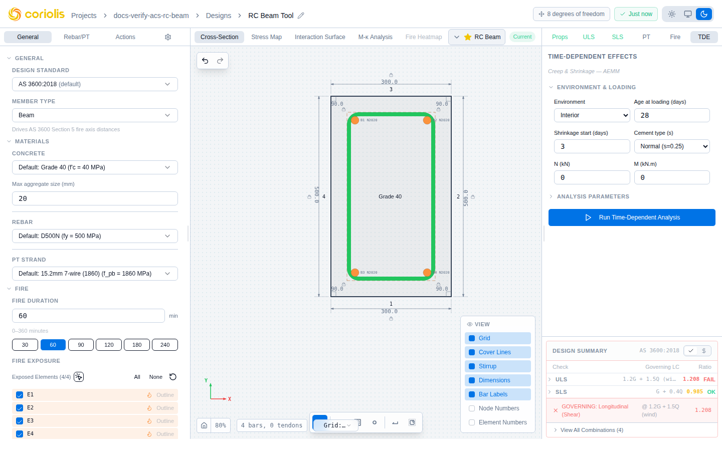
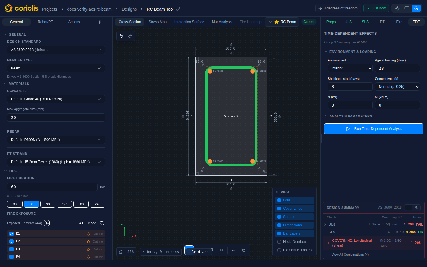
Input parameters
| Input | Description | Units | Default | Notes |
|---|---|---|---|---|
| Axial load | Sustained axial force | kN | 0 | Positive = compression |
| Moment | Sustained bending moment | kN.m | 0 | Use the quasi-permanent SLS combination |
| Age at loading | Concrete age when load is first applied () | days | 28 | Affects creep coefficient — earlier loading gives higher creep |
| Age at shrinkage start | Concrete age when shrinkage begins | days | 3 | Typically end of moist curing |
| Relative humidity | Ambient relative humidity (RH) | % | 65 | Lower RH increases both creep and shrinkage |
| Notional size | (member perimeter ratio) | mm | Auto | Set to 0 for automatic calculation from the section geometry |
| Cement type | Hardening rate coefficient | — | Normal (0.25) | Affects strength development and creep |
| Analysis ages | Ages at which to compute results | days | 28, 90, 365, 1825, 18250 | 18250 days 50 years |
| Aging coefficient | Chi factor for AEMM | — | 0.8 | Typically 0.6—0.9; 0.8 is a common approximation |
Cement type
The cement type coefficient affects the rate of concrete strength development, which in turn affects creep and shrinkage:
| Type | Coefficient | Example |
|---|---|---|
| Slow hardening | 0.20 | CEM II/B, CEM III — blast furnace slag cements |
| Normal | 0.25 | CEM I 42.5N — ordinary Portland cement |
| Rapid | 0.38 | CEM I 52.5R — high early strength |
Override coefficients
If you have experimentally measured or externally computed creep or shrinkage values, you can override the code-calculated values:
| Override | When to use |
|---|---|
| Creep coefficient override | Replace the calculated with a known value |
| Shrinkage strain override | Replace the calculated with a measured value |
Set either override to 0 to use the code-calculated value (default).
Running the analysis
Click the Run Analysis button to compute results. Unlike the other ACS checks, the time-dependent analysis does not run automatically — it is triggered manually because it requires sustained-load inputs that may differ from the ULS/SLS combinations.
Results
Time-series snapshots
The analysis generates a snapshot at each specified age, reporting:
| Output | Description | Units |
|---|---|---|
| Age | Concrete age | days |
| Creep coefficient | Cumulative creep coefficient at time | — |
| Shrinkage strain | Cumulative shrinkage strain at time | — |
| Concrete stress (top) | Top fibre stress after redistribution | MPa |
| Concrete stress (bottom) | Bottom fibre stress after redistribution | MPa |
| Steel stress | Reinforcement stress after redistribution | MPa |
| Curvature | Section curvature at time | 1/mm |
| Effective EI | Effective flexural stiffness at time | kN.m² |
Charts
Two interactive charts visualise the time evolution:
- Creep coefficient — plots over the analysis duration (logarithmic time axis)
- Shrinkage strain — plots over the analysis duration
These charts help you verify that the creep and shrinkage development follows a reasonable pattern and that the final values are consistent with your expectations for the concrete type and environment.
Interpreting results
Stress redistribution
Under sustained load, creep causes the concrete stress to reduce over time while the reinforcement stress increases to maintain equilibrium. This is a fundamental behaviour of reinforced concrete:
- Concrete stress decreases by 20—40% of the initial elastic value over the first few years
- Steel stress increases correspondingly (the reinforcement “picks up” the load shed by creeping concrete)
- The rate of change is rapid initially and asymptotically approaches a final value
Practical significance
- Deflection: The curvature at each snapshot can be used to estimate long-term deflections. The ratio of long-term to short-term curvature is approximately , reduced by the presence of compression reinforcement.
- Crack width: Increased steel stress from creep redistribution may increase crack widths under sustained load. Cross-reference with the SLS crack width check using the long-term steel stress.
- Prestress: For prestressed sections, creep and shrinkage contribute to long-term prestress losses. The loss values from this analysis should be consistent with those reported in the prestressing losses panel.
Tips and best practices
- Use the quasi-permanent SLS load combination for the sustained loads (typically where —)
- The default analysis ages (28d, 90d, 1y, 5y, 50y) cover the key milestones for most members
- If the creep coefficient exceeds 3.0, verify the inputs — this is at the upper end of the normal range and may indicate very early loading age, low humidity, or thin member geometry
- For prestressed members, the creep and shrinkage results should be cross-checked with the prestress loss calculation to ensure consistency
- The notional size is computed automatically from the section geometry when set to 0. Override it only if the member has a non-standard exposure condition (e.g., only one face exposed to drying)
Related pages
- Prestressing — prestress losses include creep and shrinkage components
- Section analysis — deflection parameters and SLS checks
- Creep and shrinkage theory — mathematical background on AEMM
- Design standards — code comparison for time-dependent effects