
Design Summary
Review ULS, SLS, and fire check results across all load combinations in the collapsible Design Summary panel. Covers accordion layout, Category Rollup badges, View All Combinations matrix, and material quantity calculations.
Overview
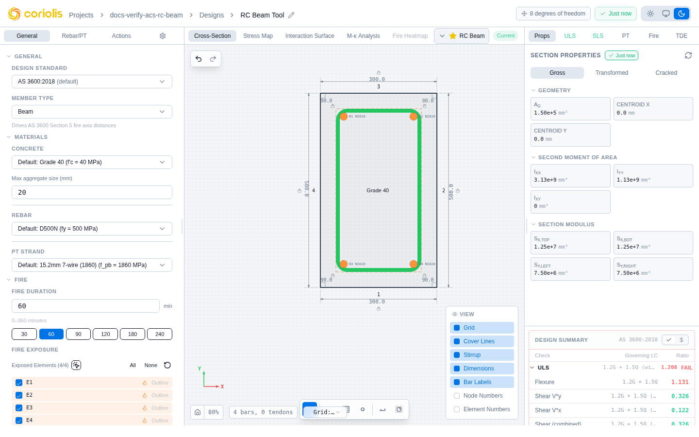
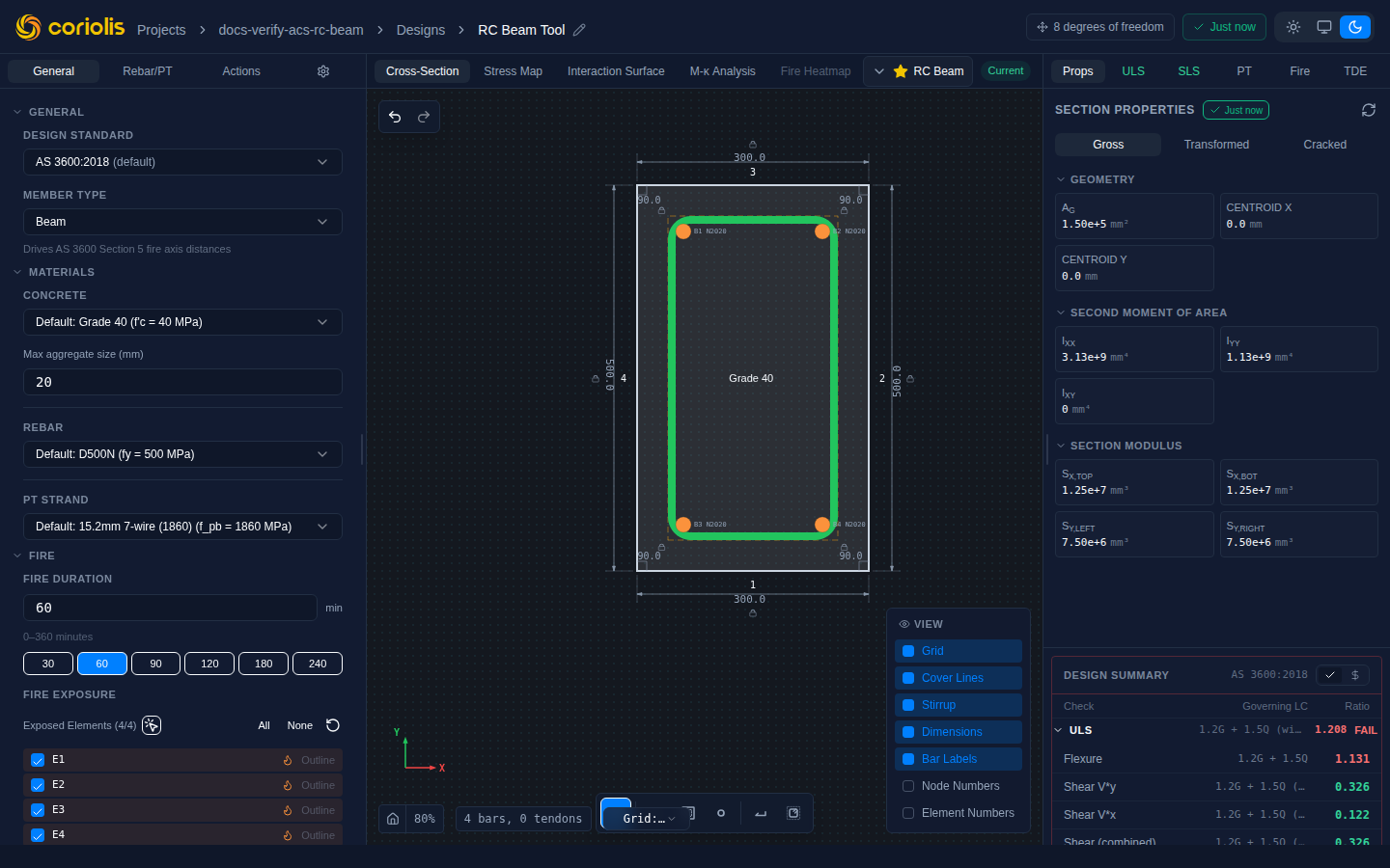
The Summary tab collects every design check result into a single scrollable panel. After running a batch analysis across multiple load combinations, the panel identifies the governing combination and utilisation ratio for each check type without requiring you to step through combinations manually.
Accordion layout
Results are organised into collapsible accordion groups, one per check category:
| Group | Checks covered |
|---|---|
| ULS — Flexure | Uniaxial / biaxial moment capacity, ductility |
| ULS — Shear | Concrete + steel shear contribution, maximum shear |
| ULS — Torsion | Torsion capacity and combined shear-torsion |
| ULS — Longitudinal force | Chord tension / compression at the flexure-shear interface |
| SLS — Stress | Concrete compressive and steel tensile stress limits |
| SLS — Crack width | Characteristic crack width per code method |
| SLS — Deflection | Effective moment of inertia, long-term factors |
| Fire | Reduced capacity at elevated temperature for the specified FRL |
All groups open collapsed by default. The first thing visible is the Category Rollup badge on each header row.
Category Rollup badges
Each accordion header shows a Category Rollup badge — the worst utilisation ratio across all load combinations in that group — with a colour indicator:
- Green (η ≤ 1.00): every combination in the group passes
- Red (η > 1.00): at least one combination exceeds capacity
Scan the full design status at a glance without expanding any accordion. Open a group only when you need the per-combination breakdown.
Per-combination breakdown
Expand an accordion group to see each load combination in that category:
| Column | Description |
|---|---|
| Combination | Load combination name or label |
| Utilisation | η = demand / capacity |
| Status | Pass (η ≤ 1.00) or Fail (η > 1.00) |
| Governing action | The critical action (M*, V*, N*, etc.) for that combination |
The governing combination — the one with the highest utilisation — is highlighted at the top of the expanded list.
View All Combinations
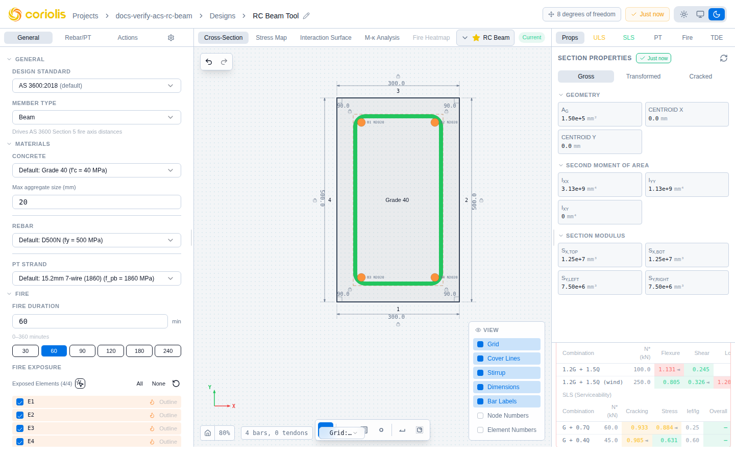
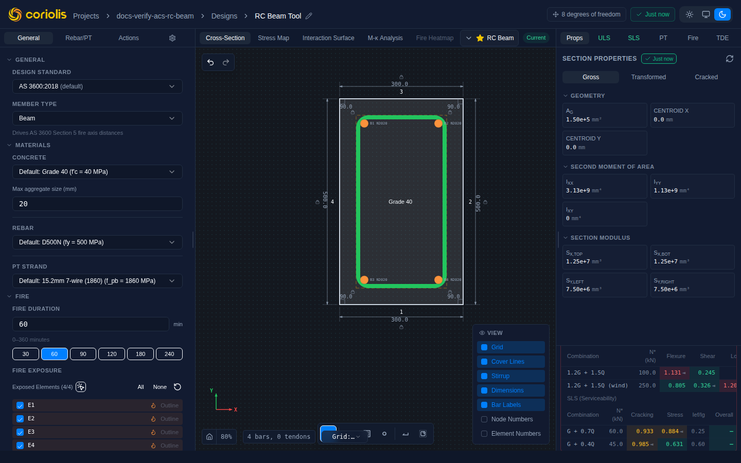
The View All Combinations section at the bottom of the panel expands to a full matrix: every load combination on one axis, every check type on the other. This is the fastest way to:
- Find combinations that govern multiple check types simultaneously
- Compare how a particular combination performs across the full design suite
- Identify check categories where all combinations pass comfortably
Click View All Combinations to expand the matrix; click again to collapse it.
Matrix cells use the same colour scale as the accordion badges: green ≤ 0.85, amber 0.85 – 1.00, red > 1.00. The amber band is a proximity warning, not a failure — only a ratio above 1.00 is a code failure. An em dash (—) indicates that a check is not applicable for a particular combination — for example, a combination with zero shear produces no shear utilisation entry.
An amber warning triangle may appear beside a passing ratio. This is an advisory — the arc-face restraint could not be confirmed — and is never a code failure; it is only ever shown on a check that passes.
Member type classification advisory
The declared Member Type (the General tab dropdown) is always what selects which member-type-scoped checks run — flexural ductility, the Cl 8.1.5 conditional-use gate, seismic hinge ductility, and the D ≥ 750 mm deep-member transverse reinforcement check. It never depends on the load level any individual combination happens to reach.
When the active design code is AS 3600-2018 and the declared type disagrees with the load level reached across the ULS envelope, the ULS group shows an advisory note beneath its check rows — for example, a section declared Beam whose worst-case combination reaches column-level axial compression (, AS 3600 Cl. 10.3.2) prompts a note suggesting the section should also be checked as a column, and a declared Column whose combinations never reach that axial level prompts the equivalent beam-side note. This advisory is not shown for EN 1992-1-1 or ACI 318-19 designs — the equivalent concept exists under those standards but the note is gated by the active design code. The note is advisory disclosure only — it never adds or withholds a check on its own; see Section analysis § Ductility applicability for what the declared type actually gates.
The same note appears in the flexure panel’s Member Type block (General tab) and in the generated PDF report’s assumptions section; all three surfaces are gated by the active design code and stay consistent.
Material quantities
Below the check results, the panel shows calculated material quantities:
| Quantity | Description | Units |
|---|---|---|
| Concrete volume | Cross-sectional area × unit length | m³/m |
| Reinforcement mass | Total steel mass per unit length (longitudinal bars + stirrups) | kg/m |
Quantities are computed for all section shapes, including curved and circular outlines. For circular columns the calculation accounts for the full circular area including arc segments.
Non-finite coordinate guard
Material quantities require all section vertices to have finite coordinates. If the section geometry contains a NaN or infinity coordinate — which can occur when parametric inputs produce a degenerate shape — ACS returns a structured error rather than propagating meaningless quantities.
The quantities panel shows an explanatory notice and the error code non_finite_coordinate in this case. To resolve it, review the section outline inputs and correct any degenerate dimension or parameter that produces a non-finite vertex position.
Related pages
- Section analysis — running ULS and SLS checks, shear and torsion design
- Reinforcement — placing bars and stirrups
- Getting started with ACS — first analysis walkthrough