
Drawing tools
CAD-style geometry input — drawing modes, vertex and arc editing, snapping, distance and angle locks, and the outline / void / inclusion region roles that drive multi-region sections.
Why this matters
Section properties are a function of geometry alone, so getting the geometry right is the whole job. The drawing tools are deliberately CAD-style — sketchy mouse work is fine for exploratory work, but precise sections want explicit distance and angle locking, snapping, and per-vertex coordinate editing. This page covers all three.
The toolbar
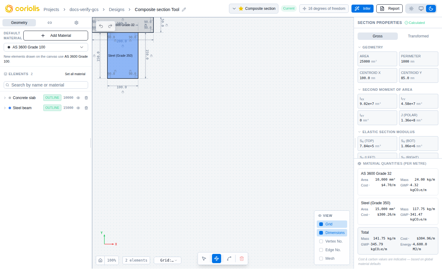
The floating toolbar at the bottom-centre of the canvas has four controls:
| Icon | Shortcut | Mode |
|---|---|---|
| Cursor | V | Select — click to select elements and vertices; drag the canvas to pan |
| Pen | P | Draw Polygon — click to place straight-segment vertices; click the start vertex to close |
| Arc | A | Draw Arc — draw circular arc segments; choose 3-point or radius mode (see below) |
| Trash | Delete / Backspace | Delete the currently selected element |
Press ESC at any time to cancel an in-progress drawing operation and return to Select mode.
Drawing a polygon
In Draw Polygon mode the canvas shows a faint preview segment from the last placed vertex to the cursor. Click to commit a vertex. The polygon closes when you either:
- Click the start vertex (the small green marker on the first vertex)
- Press the Enter key with the cursor near the start vertex (auto-close tolerance)
A polygon must have at least three vertices. If you press Enter or click-close before placing the third vertex the validator returns insufficient_vertices and the section is not analysed.
Drawing an arc segment
Press A to switch to Draw Arc mode. A mode selector appears above the toolbar letting you choose between 3-point and Radius arc gestures. You can mix arc segments and straight segments freely within a single outline — switch between the Arc and Polygon tools mid-drawing without losing the chain.
3-point arc
The simplest gesture when you know a point the arc should pass through:
- Click to place the arc start point.
- Click to capture the through-point — a point the arc will pass through (shown as a marked circle on the canvas).
- Click to place the arc end point and commit the segment.
The arc is uniquely determined by three non-collinear points. If the three points are collinear the gesture has no solution and the click is rejected with an on-canvas warning; adjust the through-point.
A single arc segment cannot sweep more than 315°. If the three-point derivation would exceed this cap, the system splits the geometry into two shorter arcs automatically.
Radius arc
Use this mode when you know the arc’s radius precisely:
- Click to place the arc start point.
- Click to place the arc end point — the chord is now fixed, shown as a dashed guide line.
- Move the cursor away from the chord (or type a number) to set the radius. The canvas shows a live arc preview and an “R 12.5 mm” label at the arc apex that updates as you move. Alternatively, type a radius value in the distance input box.
- Use the Left / Right toggle above the palette to select which side of the chord the arc bulges toward.
- Click to commit the arc (or press Enter if you typed a radius).
The minimum feasible radius for a given chord is (a semicircle). Attempting a smaller radius is rejected with a message showing the minimum value — the geometry is never silently clamped.
How arcs are encoded
Arcs are stored as a bulge value on the departing vertex:
where is the arc’s included angle. Straight segments have ; a semicircle has ; a major arc (sweep > 180°) has . The sign encodes the sweep direction: positive bulge = counter-clockwise sweep in the engineer-Y-up frame.
The centre and radius are derived on demand from the endpoint pair and the bulge — they are never stored separately, so there is no drift-capable invalid state.
Snapping
Snapping is what makes drawing precise. There are three independent snap mechanisms:
Direction lock (SHIFT)
Holding SHIFT while in Draw Polygon mode constrains the next segment to the nearest horizontal or vertical direction relative to the last vertex. Use this for rectangular sections, T-stems, flanges — anything orthogonal. The drawing-hint banner at the top-left of the canvas updates to show “SHIFT: H/V snap active” while the modifier is held.
Distance lock (type a number)
While drawing, type digits and a decimal point to lock the next segment’s length. The current value shows in a blue badge at the bottom-left of the canvas (e.g. 100 mm). Press Enter to place the vertex at the locked distance along the direction from the previous vertex to the cursor. Press Backspace to edit the value; ESC to clear it.
Combine distance lock with SHIFT to get exact orthogonal segments: type 150, hold SHIFT, move the cursor in the desired direction, press Enter.
Grid snap
The canvas has a sub-pixel snap to a fixed grid resolution (configured via gridSnap in math-utils.ts). Every cursor position is rounded to the nearest grid intersection before being committed.
Per-vertex editing
Mouse-driven drawing is good for first-cut geometry; exact sections want explicit coordinates. Every drawn element exposes a Vertices table — click the element row in the Geometry tab to expand it.
The table shows one row per vertex with editable x and y numeric inputs. For vertices where the departing edge is a curved (arc) segment, the table also shows an R column — the current arc radius in mm. Editing R reshapes the arc while preserving its sweep direction and endpoints; the minimum feasible radius is half the chord length (a semicircle), and smaller values are rejected. Edits commit on blur or Enter. The canvas updates immediately and the backend re-calculation runs automatically as soon as the new geometry validates.
You can also edit a segment’s length or an interior angle by selecting a vertex on the canvas, then editing the on-canvas dimension label. The constraint solver back-projects your edit onto the rest of the polygon, preserving locked dimensions and angles where possible.
Region roles
Every element carries a role that determines how it contributes to the section. Pick the role from the dropdown on the element row in the Geometry tab.
| Role | Effect on the calculator | Material constraint |
|---|---|---|
| Outline | Adds area, first and second moments to the section integrals (sign +1). Sets the reference material when composite. | Must have a material assigned |
| Void | Subtracts from the same integrals (sign −1). Holes, openings, lightening cuts. | Material is ignored |
| Inclusion | Adds with sign +1 in the adjacent case (textbook composite-beam stack — inclusion shares at most a boundary with the outline, never interior area). The transformed-section path applies the modular ratio of the inclusion’s material against the outline’s. Embedded inclusions (rebar inside concrete, plates inside a host shape) are planned but not yet shipped — see #1748. | Must have a material assigned |
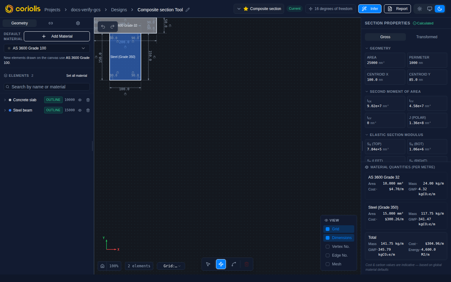
An inclusion today must be adjacent to an outline — it shares at most a boundary with every outline and never overlaps interior area. Calculator-equivalent to a second outline, used for semantic labelling of a secondary positive-sign region (e.g. a steel beam sitting on top of a concrete slab, modelled as concrete outline + steel inclusion).
The strictly-contained layout (inclusion fully inside one outline — the rebar-in-concrete / plate-in-host-shape case) is planned but not yet shipped: any outline+inclusion overlap, including strict containment, is currently rejected with overlapping_regions. Tracking issue: #1748. For reinforced-concrete design with proper strain compatibility (concrete cracking + rebar yielding), the Advanced Concrete Section is the right tool today; the Section Analyzer only solves the linear-elastic transformed-properties problem and currently only for adjacent layouts.
Region validation enforces these physical rules at the backend:
- Polygons must not self-intersect. Returns
self_intersection. - Voids must lie strictly inside an outline. A void escaping its outline returns
void_outside_outline. - Outlines must not overlap each other. Two outlines that share interior area returns
overlapping_regions. - Inclusions must be fully outside every outline (adjacent). Any outline+inclusion overlap — including strict containment — returns
overlapping_regionstoday; the embedded case is planned under #1748. Two inclusions sharing interior area, or an inclusion sharing area with a void, also returnsoverlapping_regions. - Voids must not overlap each other. Overlapping holes would be double-counted by the subtractive integration.
When voids or inclusions are present without an enclosing outline you get no_outline. Three vertices is the minimum for any region (insufficient_vertices); coordinates must be finite (non_finite_coordinate).
For a worked example combining all three roles, see Worked example: composite section.
View options
The bottom-right View Options panel toggles four overlays on the canvas:
| Toggle | What it shows |
|---|---|
| Dimensions | Edge-length labels on each segment and interior-angle labels at each vertex |
| Vertex No. | Numeric labels next to each vertex matching the row index in the vertex table |
| Edge No. | Numeric labels along each edge — useful when cross-referencing with a tabulated input list |
| Mesh | A finite-element mesh overlay (triangulation). The mesh is generated server-side and exposed for visual inspection of where future stress-field outputs would be sampled. |
Vertex and Edge numbers are useful when collaborating over a screenshot or filing a bug — they give you a stable way to reference “the third edge from the top” without ambiguity.
Status bar
The bottom-left status bar always shows the current zoom level (as a percentage) with a home icon that zooms-to-fit the current geometry. While drawing it additionally shows the cursor coordinates and the distance-lock badge (when active).
Keyboard reference
| Key | Action |
|---|---|
| V | Switch to Select mode |
| P | Switch to Draw Polygon mode |
| A | Switch to Draw Arc mode |
| SHIFT (held) | Horizontal/vertical snap while drawing |
| 0-9, . | Lock the next segment’s length |
| Enter | Place vertex at the locked distance (when distance is locked) |
| Backspace | Edit the distance-lock value, or delete the selected element |
| Delete | Delete the selected element |
| ESC | Cancel the in-progress polygon and return to Select |
Next steps
- Parametric sketcher — apply dimensional and geometric constraints to keep geometry correct as you edit
- Materials — assigning materials and what each region’s material means
- Section properties — what the analyser reports once the geometry is committed