
Fire design for concrete sections: when the tables are enough, and when to calculate
AS 3600 lets you establish a fire resistance period from the Section 5 tables or by calculation. We ran the same column through both at FRL 120, 180 and 240 to find out when calculating pays for itself.
AS 3600:2018 gives you two ways to show that a concrete member survives a fire. Clause 5.3.1 says the fire resistance period “shall be established by either one of the following methods”: (a) from the tabulated data in Section 5, or (b) “predicted by methods of calculation”. Most engineers use the tables, and most of the time that is the right call.
We wanted to know when it stops being the right call. So we took one heavily loaded office column and ran it through both routes in ACS at FRL 120, 180 and 240. The short version:
- At FRL 120 the tables cost nothing. Both routes pass the same 500 mm column with the same 40 mm cover.
- At FRL 180 the tables cost 4 mm of cover and nothing else, so the section materials, the cost and the embodied carbon come out the same.
- At FRL 240 the tables need a bigger column. Calculation passes a 500 mm column. The tables need 550 mm with extra bars, which is 23 % more cost and 24 % more embodied carbon in the section materials.
This post walks through how ACS does fire design, which method it starts you on and why, both worked examples, and what you take on when you choose to calculate.
What a fire does to a concrete section
Concrete is a good insulator, which is exactly why it performs well in a fire. Heat soaks in from the exposed faces slowly, so the outer layer gets very hot while the core stays cool for a long time. Both materials lose strength as they heat up. EN 1992-1-2 tabulates the reductions: for concrete (Table 3.1) and for reinforcing steel (Table 3.2a). The bars matter most, and they sit in the hot outer layer behind the cover.
ACS works this out with a 2D finite element heat transfer analysis of the actual section, for the fire curve, duration and exposed faces you set.
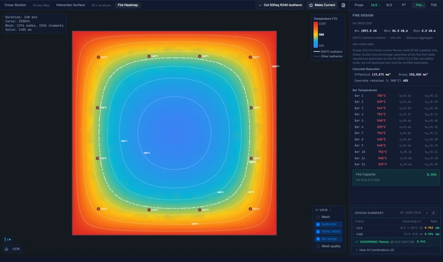
After four hours in the 500 mm column, the corner bars sit at about 755 °C and keep roughly 16 % of their ambient yield strength. The concrete core is still cool.
The three fire methods in ACS
| Method | Where it comes from | What it gives you |
|---|---|---|
| AS 3600 Section 5 (tabulated), the default | AS 3600:2018 Section 5, the Cl 5.3.1(a) route | PASS, FAIL or NOT ASSESSED, with demand/supply ratios on section width and axis distance |
| 500 °C isotherm | EN 1992-1-2 Annex B.1, a Cl 5.3.1(b) calculation | A fire-reduced interaction surface and a utilisation check against your fire actions |
| Advanced fibre | EN 1992-1-2 §4.3, a Cl 5.3.1(b) calculation | The same outputs, integrated fibre by fibre over the temperature field |
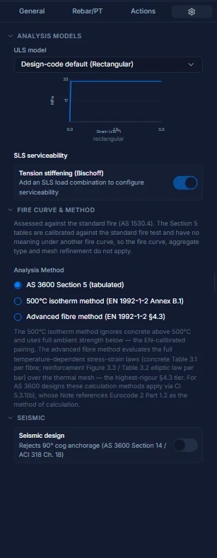
The tabulated method looks up the minimum section width and the minimum axis distance to the reinforcement for your member type and FRL, then compares them with your section. For columns the table also depends on the fire load level , which ACS computes from your fire load combination.
The 500 °C isotherm method discards all the concrete hotter than 500 °C, treats the rest at full ambient strength, and reduces each bar’s strength for its own temperature. That gives an interaction surface for the fire limit state, which ACS checks your fire actions , and against. The method is only valid down to a minimum section width (EN 1992-1-2 Table B1: 160 mm at R120, for example), and ACS refuses to run it on a narrower section rather than return a number from outside its range.
The advanced fibre method keeps every fibre of concrete and steel and integrates its temperature-dependent stress-strain law directly. It has no Annex B width limit. It is also slower, and it usually returns a higher capacity than the isotherm method, so you choose it deliberately.
Why the tables are the default
The two routes in Cl 5.3.1 carry different obligations. For the tables, the clause says that “no further checks are required concerning shear and torsion capacity or anchorage details”. For calculation, “checks shall be made for bending, and shear, torsion and anchorage capacities as required”.
The fire capacity check in ACS covers axial force and biaxial bending (N–M interaction). It does not check shear, torsion or anchorage at the fire limit state. So a calculation-route PASS in ACS is part of a compliance argument, not all of it, while a tabulated PASS is complete. We think a new design should start on the route whose answer is complete. Taking on the extra checks should be your decision, not a default. The fire results panel says this every time you are on a calculation method.
When the tables have no entry for your section, ACS reports NOT ASSESSED and recommends a calculation method: the 500 °C isotherm if your section is wide enough for it, otherwise advanced fibre. It never switches for you.
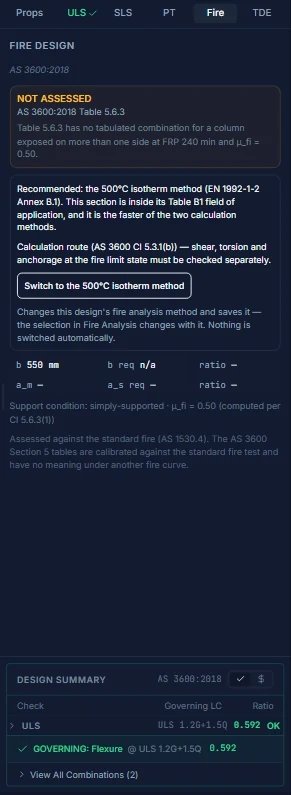
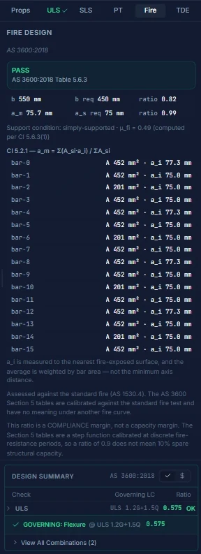
This is the 550 mm column from the FRL 240 example below. The panel shows rounded to 0.50, but the computed value is 0.5006, just above the table’s 0.5 column. We’re changing the display so the value makes clear which side of the column it falls on.
Where calculation is, and is not, open to you
Both routes are part of AS 3600, so a calculation under Cl 5.3.1(b) is as much a part of the standard as the tables. Note 1 to that clause names Eurocode 2 Part 1.2 as a method of calculation, and that is what ACS implements. Two clauses narrow the choice for particular members, and we would rather you heard about them from us.
Braced columns. Cl 5.6.2 says the fire resistance period for braced columns “shall be determined using either Clause 5.6.3 or Clause 5.6.4”, which are the two tabular methods. Those clauses then say the period “may be determined” from their tables, and that columns outside their limits must use “alternative design approaches, as specified in Clause 5.3.1”. Our reading is that Cl 5.6.2 chooses between the two tables when you are on the tabular route. It does not take Cl 5.3.1(b) away from braced columns. A stricter reading is possible, though: that a braced column inside the Cl 5.6.3 or 5.6.4 limits must use the tables. If you intend to justify a braced column by calculation, agree that reading with your building certifier first.
Flat slabs. Cl 5.5.2(b) is explicit: the minimum flat-slab thicknesses in Table 5.5.2(A) “cannot be reduced by calculation methods in accordance with Clause 5.3.1(b)”. The fire check in ACS also does not cover punching shear. The calculation methods are not the right tool for sizing a flat slab for fire, so use the tables.
Worked example A: a heavily loaded office column
The column
- Loads: a braced interior column supporting five office floors on an
8.4 m × 8.4 m grid, with G = 7.0 kPa, Q = 3.0 kPa and = 0.4.
- Fire combination (G + Q): = 2893 kN, = 86.8 kNm (e = 30 mm).
- Ultimate limit state (1.2G + 1.5Q): = 4551 kN, = 136.5 kNm.
- Materials: f’c = 40 MPa, D500N bars, siliceous aggregate.
- Detailing: 40 mm cover to N10 ties, with cross-ties so every bar is restrained (Cl 10.7.4.1).
- Fire: ISO 834 on all four faces.
Ambient strength sets the size. At ambient conditions the column needs to be 500 mm square with 12 N24. A 400 or 450 mm section fails the ultimate limit state. So every fire comparison below starts from 500 mm square.
The Cl 5.6.3 limits, checked by hand. Table 5.6.3 applies only within the Cl 5.6.3 limits:
- bars on all faces where As ≥ 0.02Ag and the FRP is over 90 minutes;
- effective length in fire under 3 m;
- eccentricity no more than 0.15b;
- As no more than 0.04Ag.
ACS is a cross-section tool. It does not know the column’s length, so it cannot check the length limit, and it does not currently check the other three. We checked all four by hand for every section here, assuming a 3.0 m storey and an effective length in fire of 0.7 × 3.0 = 2.1 m. Every section is within the limits. You will need to do the same.
Interpolation. Cl 5.3.2 allows linear interpolation in the Section 5 tables. For this column = 0.589, which falls between the table’s 0.5 and 0.7 columns. ACS currently rounds up to the next column, which is conservative. Below we give both ACS’s answer and the interpolated one, and we base each comparison on whichever is less onerous. We are not trying to make the tables look worse than they are.
FRL 120: no difference
At 500 mm square with 40 mm cover, the average axis distance to the bars is 62.8 mm.
- Tables: the section needs 51 mm of axis distance as ACS runs it (44.9 mm interpolated). PASS, governing ratio 0.81 (0.72 interpolated).
- 500 °C isotherm: PASS, utilisation 0.39.
The same column passes both ways, so calculating gains nothing.
FRL 180: a few millimetres of cover
- Tables: at = 0.589 the interpolated axis distance is 66.1 mm (70 mm as ACS runs it). With 40 mm cover the column falls short. It needs 44 mm of cover by interpolation, or 48 mm as ACS runs it.
- 500 °C isotherm: PASS at 40 mm cover, utilisation 0.48.
A few millimetres of cover doesn’t change the section’s material quantities, so the cost and the embodied carbon are identical. We also ran a simply supported 400 × 650 mm beam at FRL 180 and 240 as a check. It told the same story: the tables asked for more cover and nothing else.
FRL 240: a bigger column
Table 5.6.3 has no entry at FRL 240 for a column exposed on more than one side at = 0.7. To use the tables at all, has to come down to 0.5 or less, and interpolation can’t help, because there is nothing at 0.7 to interpolate towards. Our 500 mm column sits at 0.589.
The load stays the same, so the only way to lower is to add capacity. A 550 mm column with the same 12 N24 lands at = 0.5006, just over the line, and ACS reports NOT ASSESSED. The leanest section we found that passes the tables is 550 mm square with 12 N24 + 4 N16 and 53 mm cover, at = 0.487 and a governing ratio of 0.99 (0.98 interpolated). The same 500 mm column with 40 mm cover passes the 500 °C isotherm check with a utilisation of 0.59.
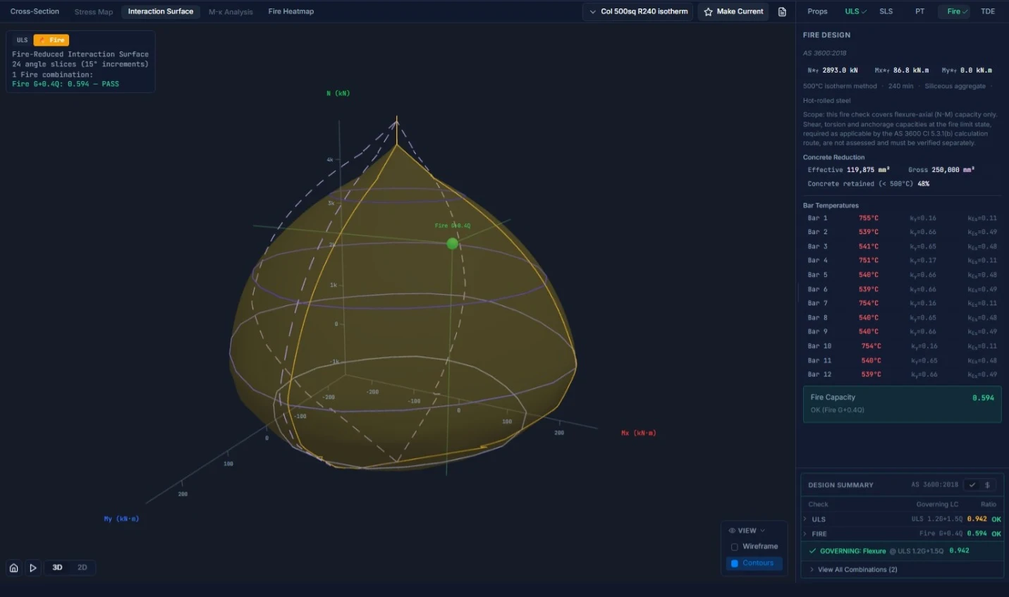
Here is what that difference costs, for the section materials only:
| Per metre of column | Calculation (500 mm, 12 N24) | Tables (550 mm, 12 N24 + 4 N16) | Difference |
|---|---|---|---|
| Mass | 655 kg | 795 kg | +21.5 % |
| Cost | A$201.92 | A$248.52 | +A$46.60 (+23.1 %) |
| Embodied carbon (A1–A3) | 240.2 kgCO₂e | 296.9 kgCO₂e | +56.7 kgCO₂e (+23.6 %) |
These figures come from the ACS material catalogue:
- Carbon: EPiC hybrid life cycle assessment factors (concrete 40 MPa, 497 kgCO₂e/m³; steel bar 2.1 kgCO₂e/kg).
- Cost: indicative 2026 Australian market rates (A1,400/t reinforcement).
They cover the concrete and steel in the section. Formwork, labour and everything else are not included. ACS labels these totals “an inventory, not a comparable figure”, because the catalogue materials do not declare a uniform reporting basis. Both options use the same two materials from the same sources, so the percentage difference between them holds, but don’t set the absolute numbers against figures from another tool.
What the calculation route asks of you in return
The 23 % isn’t free. On the calculation route you must also check shear, torsion and anchorage at the fire limit state (Cl 5.3.1(b)), and ACS doesn’t do that for you. For a braced column with this little eccentricity those checks rarely govern, but they have to be done and recorded. There is also the Cl 5.6.2 question above to settle with your certifier.
One more reading note. The isotherm utilisation of 0.59 does not mean 41 % spare capacity. ACS reports the larger of two ratios: the moment ratio at constant axial load, and the axial load over the fire squash load. Here the axial ratio governs. Measured along the line of the load’s eccentricity, the same column sits at about 0.81.
Worked example B: when only the advanced method applies
Precast floors often use T-beams with slender webs, and slender webs are where both simplified methods run out.
The beam
- Section: a precast T-beam with a 600 × 100 mm flange, a 150 mm web, 500 mm overall depth, and 2 N20 bottom bars at 30 mm cover.
- Span and loads: 8.4 m simply supported at 600 mm centres, with a 60 mm topping. The fire moment is = 44.7 kNm.
- Fire: ISO 834 for 120 minutes. The top face is protected by the topping, and the flange soffits are exposed.
The tables fail it. At FRL 120, Table 5.4.1(A)‘s narrowest permissible web is 200 mm, so a 150 mm web satisfies none of its combinations: FAIL, width ratio 1.33. A FAIL is not a NOT ASSESSED. The tables do cover beams, and this one is too narrow.
The 500 °C isotherm method refuses it. EN 1992-1-2 Table B1 limits the method to sections at least 160 mm wide at R120. ACS measures the web at 151.6 mm and declines to run, explaining that “below the tabulated width the method’s error is a step function of geometry rather than a bounded approximation”. It offers the advanced fibre method instead.
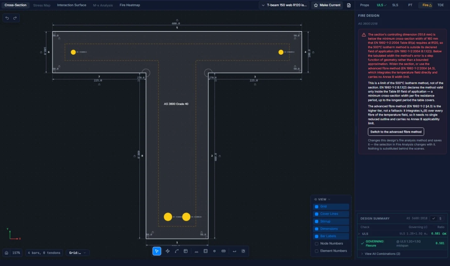
The dimensions on the canvas show the problem: a 600 mm flange made of two 225 mm outstands either side of a 150 mm web. The web is the limb that fire attacks from both sides, and Table B1 measures that limb, not the flange.
The advanced fibre method gives an answer, and it’s a fail. With 2 N20, the bottom bars reach about 710 °C and keep about 22 % of their yield strength. The fire moment capacity is 30.1 kNm against a demand of 44.7 kNm: FAIL, utilisation 1.48.
Add a second layer and it passes. A second pair of N20 bars, 42 mm above the first, sits in cooler concrete at about 627 °C. That lifts the fire moment capacity to 81.7 kNm: PASS, utilisation 0.55. Both versions of the beam pass at ambient.
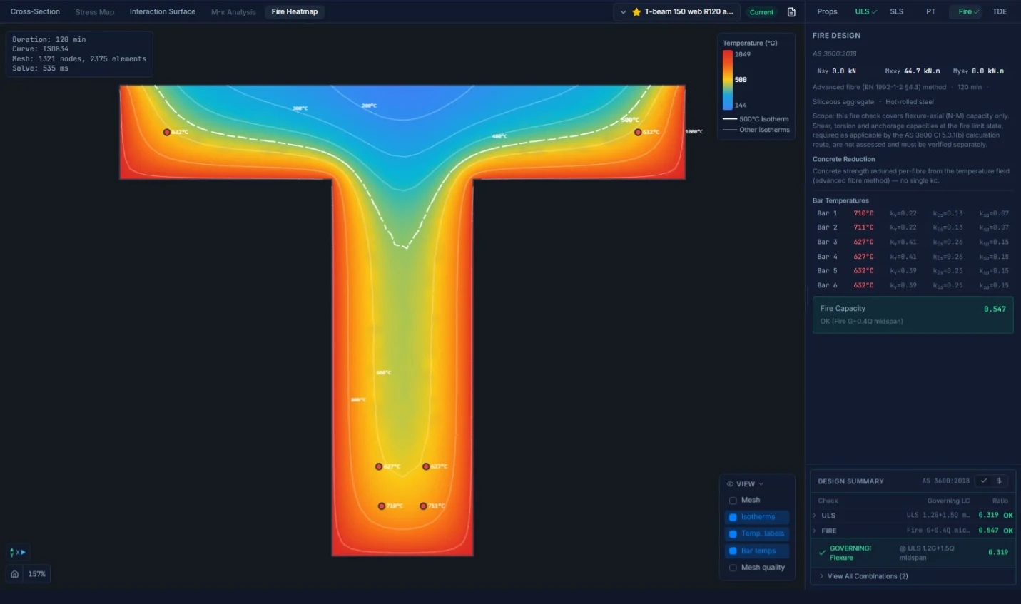
The dashed line is the 500 °C isotherm. After two hours almost the whole web is hotter than that, and only the flange and the top of the web stay cooler. The isotherm method would discard nearly all of the web, which is why EN 1992-1-2 doesn’t allow it on a section this slender.
That is the calculation route doing something the tables can’t: showing whether a section the tables reject can still carry its fire load. The same Cl 5.3.1(b) obligations apply to shear, torsion and anchorage.
Choosing a route
- Start with the tables. They are complete, quick, and at common FRLs they often cost you nothing. That is why ACS starts you there.
- Calculate when the tables fall short: a NOT ASSESSED verdict, a high FRL, or a heavily loaded column where the table forces a bigger section. Then compare the cost of the extra section against the cost of the shear, torsion and anchorage checks you take on.
- Don’t calculate your way out of a flat slab’s minimum thickness, and settle the braced-column reading with your certifier before you rely on it.
The fire design guide covers every input, table and refusal in detail.